• projects.
    • neon space moon.
    • the shape of refractive memory.
  • places.
    • new york.
    • bali.
    • paris.
    • los angeles.
    • australia.
    • japan.
    • sedona.
    • england.
  • people.
    • sports.
    • portraits.
    • events.
  • things.
    • wildlife.
  • itp blog.
    • itp_general.
    • itp_icm_f18.
    • itp_physical computing_f18.
    • itp_video&sound_f18.
    • itp_visual language_f18.
    • itp_animation_f18.
    • itp_wearables_s19
    • itp_fandom_s19
    • itp_turning_s19
    • itp_uxdesign_s19
    • itp_fungus_s19
    • itp_softrobotics_s19
    • itp_augmentedreality_f19
    • itp_fabrication_f19
    • itp_light&interactivity_s20
  • connect with me.
  • Menu

Madshutter Photo

  • projects.
    • neon space moon.
    • the shape of refractive memory.
  • places.
    • new york.
    • bali.
    • paris.
    • los angeles.
    • australia.
    • japan.
    • sedona.
    • england.
  • people.
    • sports.
    • portraits.
    • events.
  • things.
    • wildlife.
  • itp blog.
    • itp_general.
    • itp_icm_f18.
    • itp_physical computing_f18.
    • itp_video&sound_f18.
    • itp_visual language_f18.
    • itp_animation_f18.
    • itp_wearables_s19
    • itp_fandom_s19
    • itp_turning_s19
    • itp_uxdesign_s19
    • itp_fungus_s19
    • itp_softrobotics_s19
    • itp_augmentedreality_f19
    • itp_fabrication_f19
    • itp_light&interactivity_s20
  • connect with me.
wl6nzq39TriRoWN5IQNjMg.jpg

Week 6 | Motors

October 16, 2019

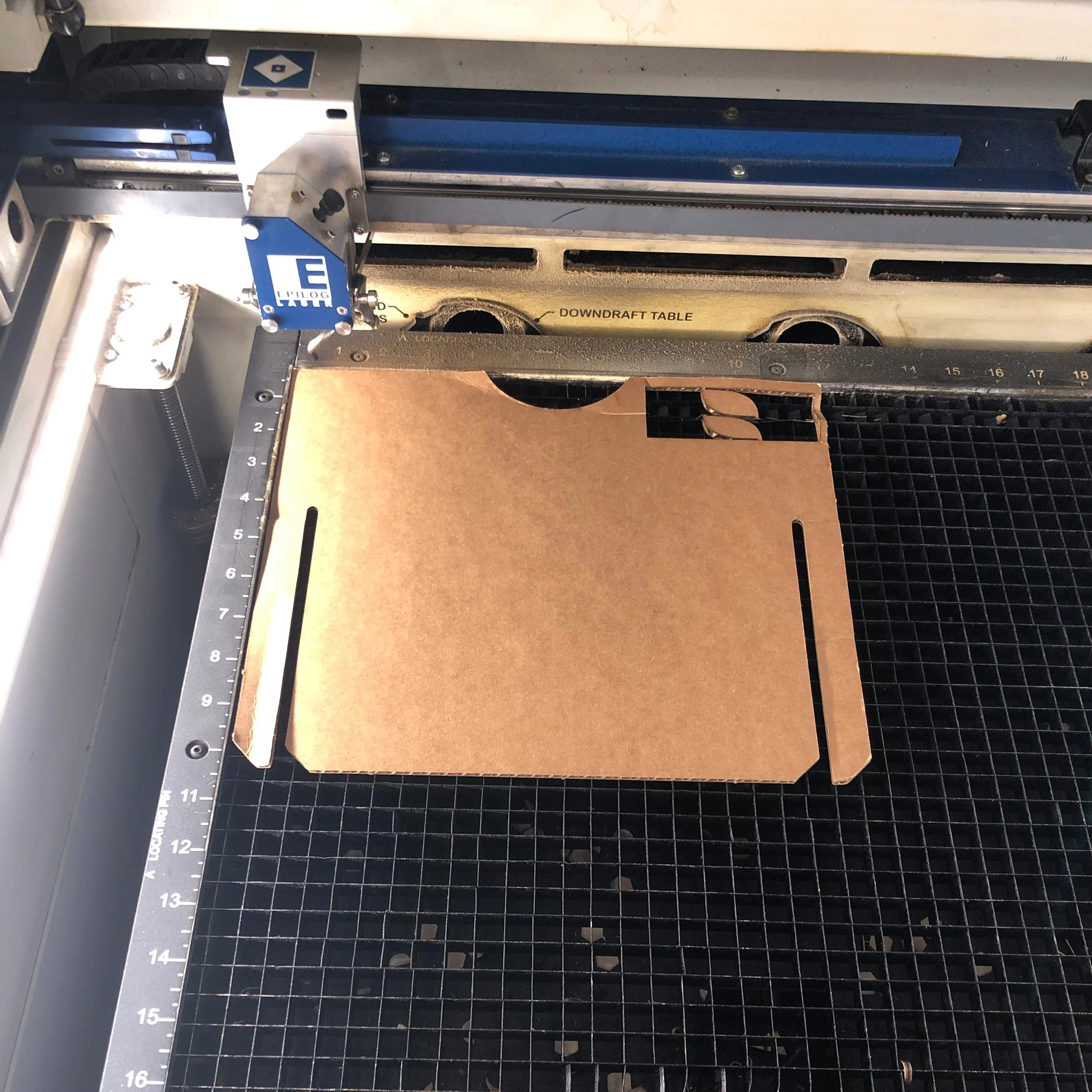
This week, I attached a motor to the enclosure without a purpose to give it a purpose. To do this, I found a DC motor from my Arduino kit from last year and I gathered the necessary materials, and purchased a 9v battery holder and screws from Tinkersphere. I used a cardboard cutout of the star from my first project; and assembled per the below steps;

1a. marked holes of base of wood enclosure

used a pointed object (sharp tweezers in this case) to make markers matching the battery holder below

uPzpY73EQ%25Skmoa9wIvn2w.jpg

1b. 9v battery holder

used to make markers in wood enclosure

EDH4GDv6SWGWXLczLneTMQ.jpg

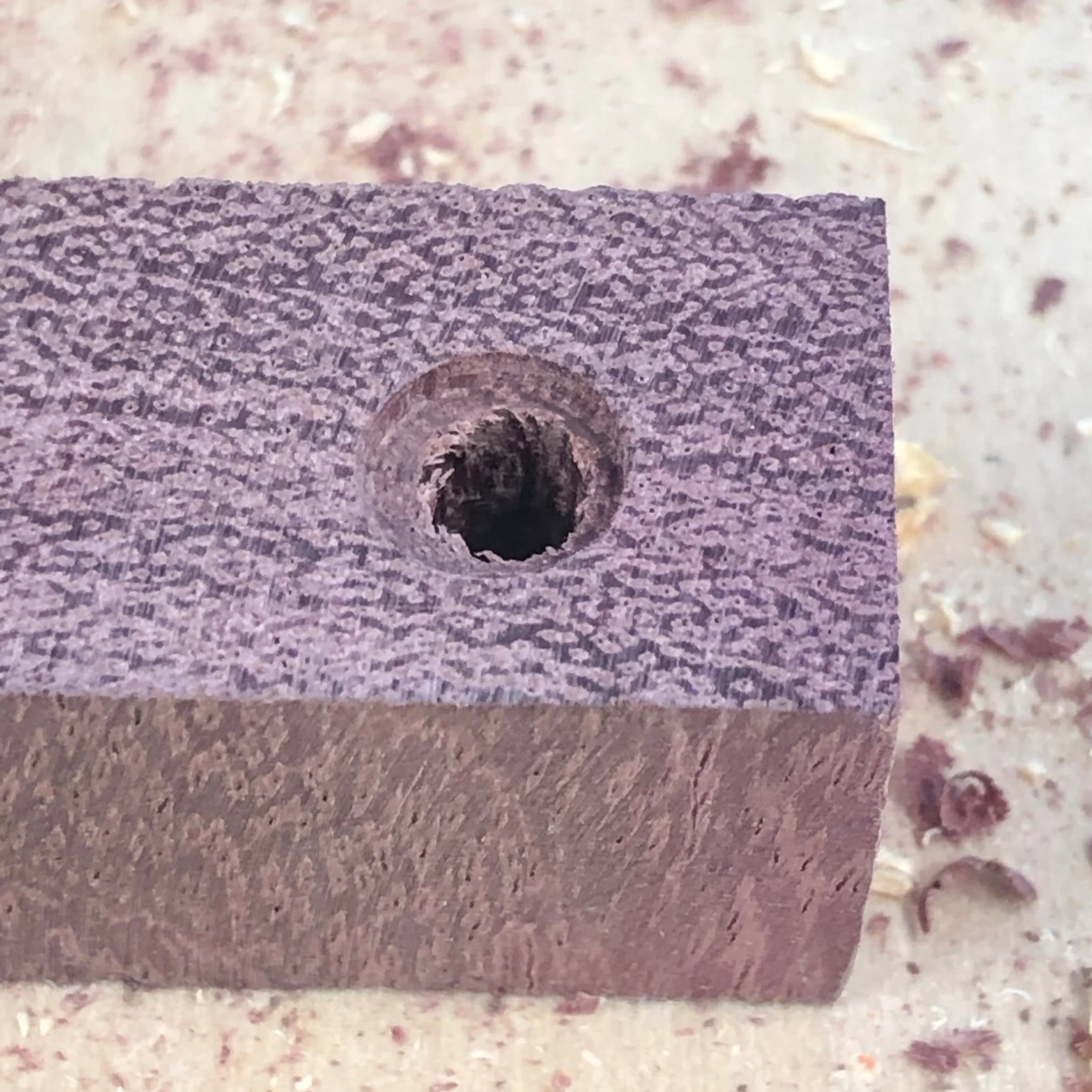
2a. hand drill with 1/16” bit

drilled holes for brass wood screws

2b. drilled holes in markers

using hand drill with 1/16” bit

SbNLjlNqSEG6xEjHAeJK8w.jpg

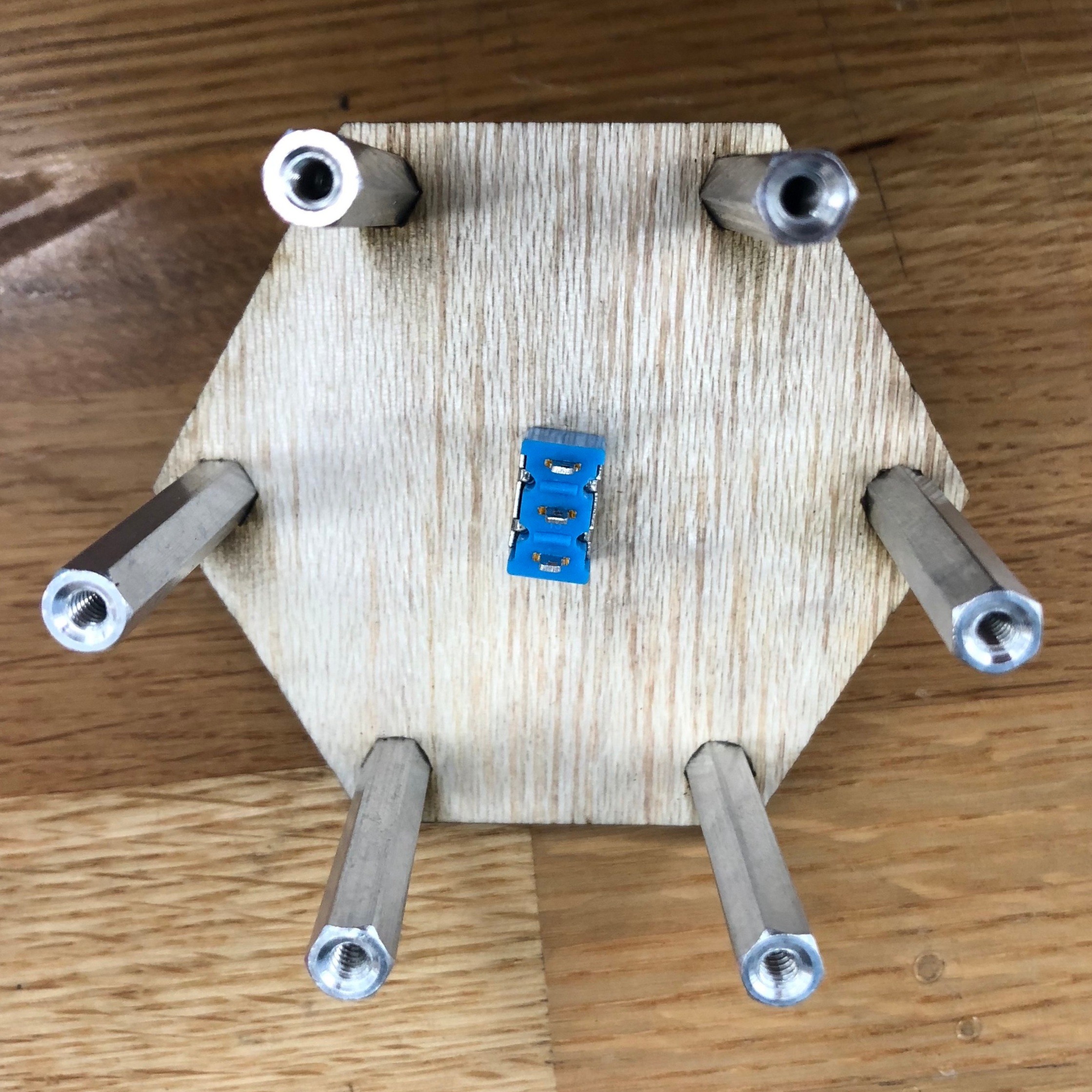
3a. brass wood screws

used to fasten 9v battery holder to wood enclosure

Y%25HgESGfRTy%258hhtPkq9hQ.jpg

3b. 9v battery holder

fastened to wood enclosure

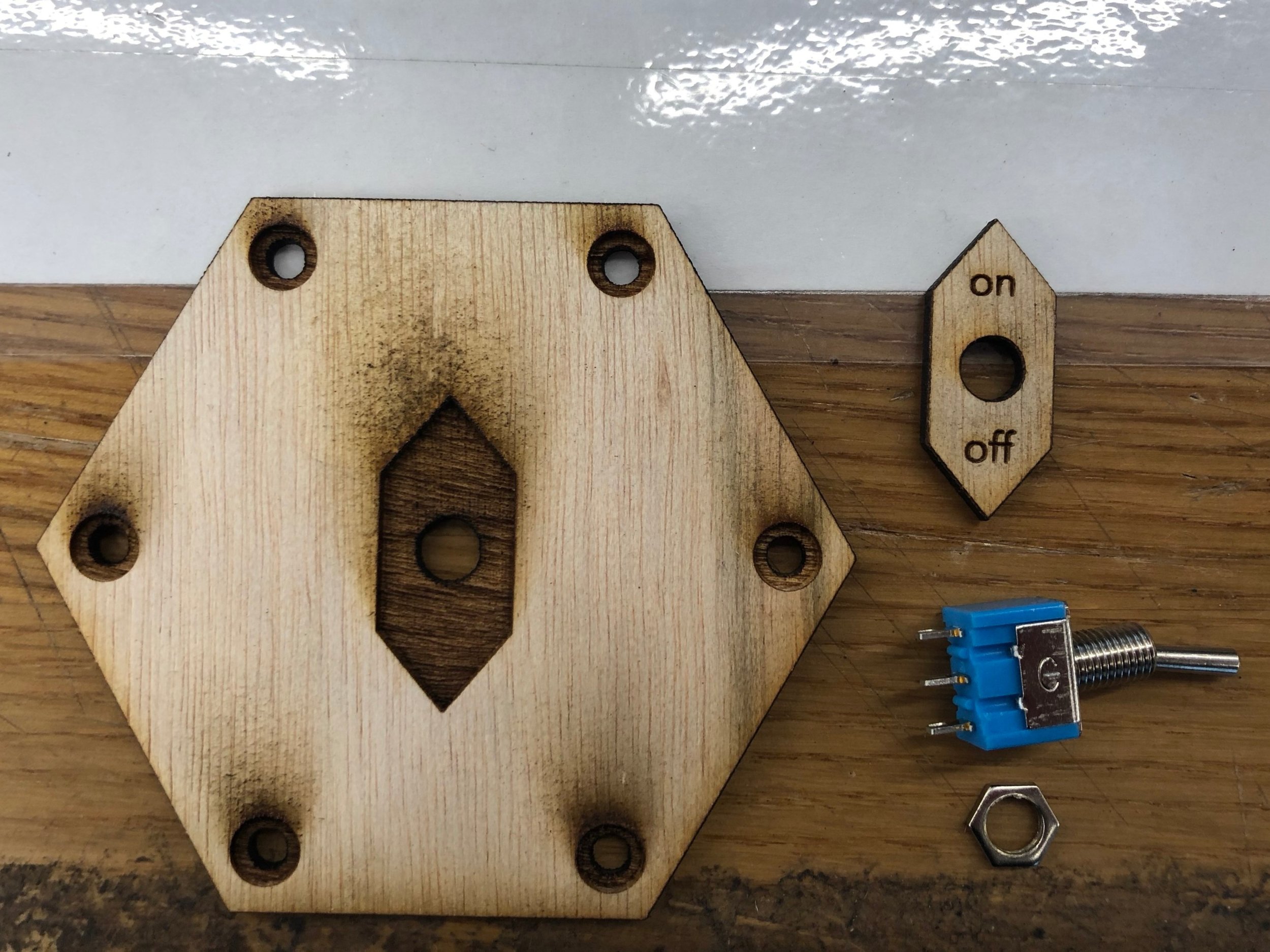
4. solder wires to switch and power source

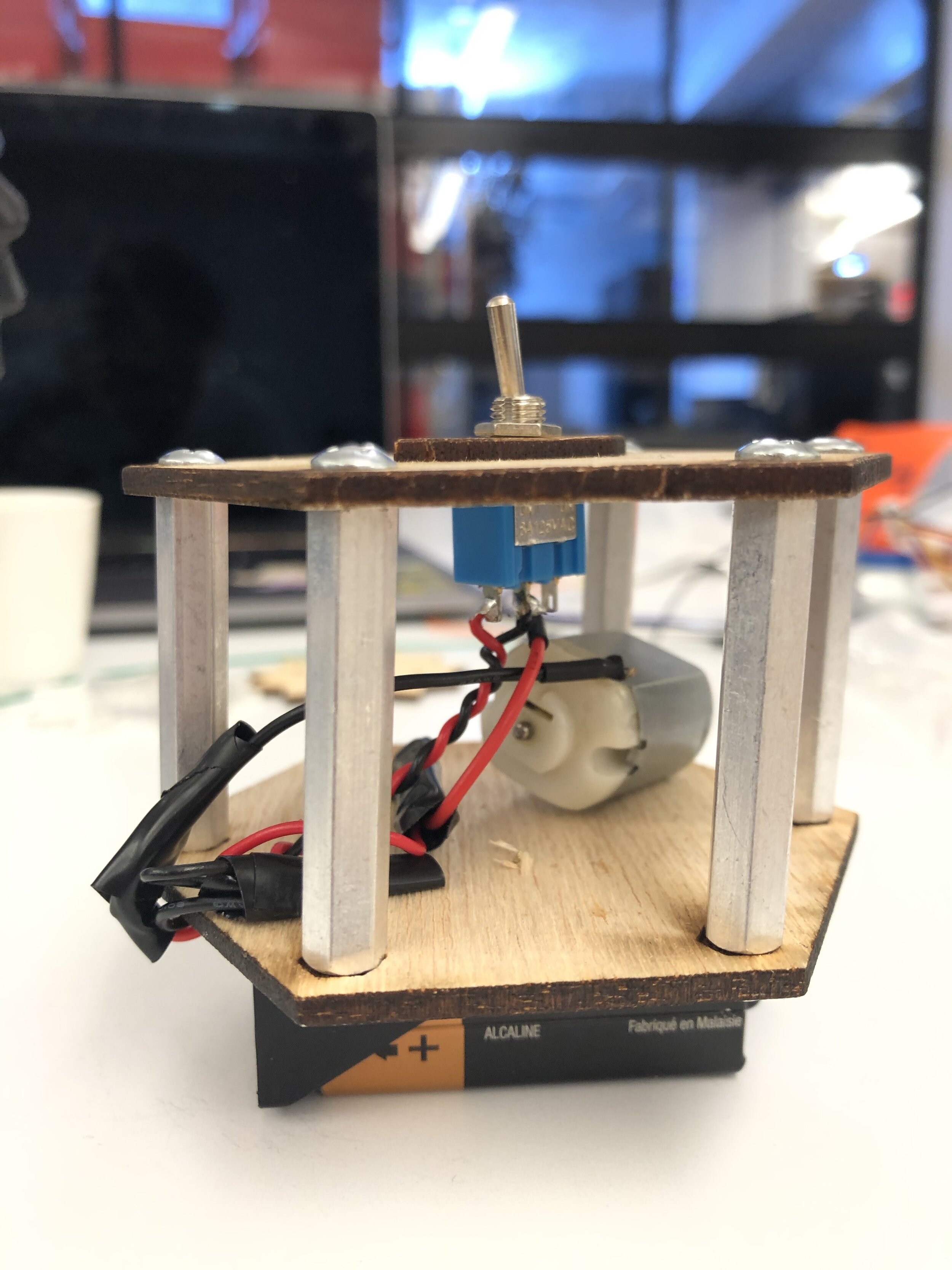
5. solder power source to motor

cv+eh%YdQ7CXhIk6ZvFaxw.jpg

6. locate location for motor

YpIuG6HSTm%2BG%2BAR2SMClaA.jpg

7. application of hot glue to stabilize star to motor

AbwGZTfDTZ28L8OCgE%25tZg.jpg

8. application of hot glue to stabilize motor to wooden enclosure
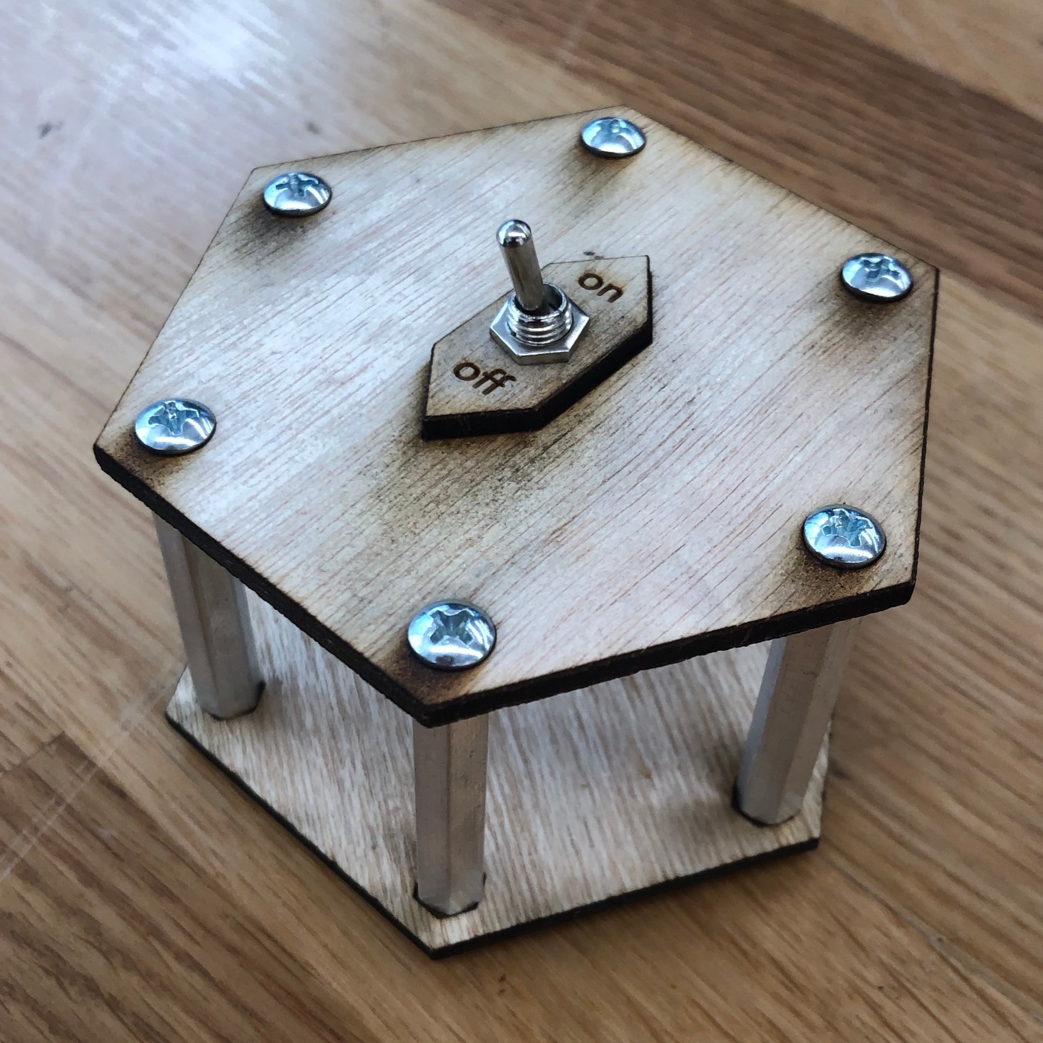
MwurvESFTvGaPqlZrfRaIQ.jpg

project, complete.

orientation designed for a hand-held enclosure with switch to direct ‘on’ pointed towards moving star

Comment
MrVkxRJWQZCkEdWM7OiKCw.jpg

smokeless peace pipe

incense holder

Week 5 | Materials & Fasteners

October 08, 2019

I started this project out with the idea of an incense holder in mind. For this week’s project of combining materials, I chose to use a mix of woods (walnut and purple heart) along with brass and cork. I first went through my existing pieces of scrap from my wedges project and found a pyramid-like shape cut that seemed to go along nicely for this concept.

I went to a hardware supply store and found 1/8” brass tubing that would easily work for the concept of holding the incense at a desired angle and direction. The problem with my current incense holder is precisely that issue — misguided direction.

I considered just flattening the edge of the pyramid and having the brass tube come out of one side, but I had the Purple Heart wood just sitting there, asking to be used for something. So I took it to the miter saw and just cut a simple 3/4” piece, as the wood panel itself was 4” x 3/4” x 12”.

I assembled the pieces together using a brass wooden screw and used cork feet to cover the fastener. The only adhesive used in the project was the one included on the cork feet, and all other connections are hardware based. Steps of process are below.

QKlr22oUSTyJu9IpDov%2B5w.jpg

1. collect wood specimens

s3BpBIWQSI%2BIyNIlquZvwQ.jpg

2. pilot hole in pyramid shape

using drill press

fId%Bw5bTEWGnhRhFdtmnw.jpg

3a. align angular pilot hole

using drill press and scrap wood turned into jig

hmuI%25f02T0aCf6PAG35Zvw.jpg

3b. angular pilot hole completed

1MJoA%2BsFSqW25YhIjWmKcg.jpg

4. test fitting

brass tube fits snugly in at proper angle

5. pilot hole in base

using drill press for fastener to connect pyramid shape

6oneNBtIStafbG2y3xv3eQ.jpg

6. drill out inlet

for brass screw head

5MPPpFcPSly1tkWTDOXpNQ.jpg

7a. assembly

brass screw to fasten pieces together

BFTEZm2rSy29qm%eOYnTug.jpg

7b. assembly

cork feet applied

8nNtMRB9RtSrCWKSOEScYw.jpg

assembly complete.


2 Comments
T5Nv9GYCQomOvykHijVdzQ.jpg

Week 4 | Enclosures

October 01, 2019

This week for the enclosures project, I wanted to use the principles we learned this week regarding standoffs and enclosures for components. I went the cheap option (ie FREE) and used the supplied hardware and components in the shop and found scraps of wood to cut on in both the Maker Space and ITP Shop.

I used a digital caliper to measure the hardware and then drew a vector illustration in Adobe illustrator to build out the shape and wanted to include instruction for the chosen switch. I went with a hexagon shape and created inlets for the hardware as well.

llRZtU6KQzCPZZPNArTMYw.jpg

1. digital caliper

to measure hardware

HrE65QfiRpGLX%254tdB5xag.jpg

2. recorded measurements

of hardware and component requirements

Screen+Shot+2019-10-01+at+8.04.51+PM.jpg

3. illustrator design

to print/engrave/cut via laser printer

bYWwPzmHTYasSq%2BRlgJ%250Q.jpg

4. laser-cut/etch

front of birch wood

MttRoZh7Q9W8svW8F7%2BlQw.jpg

5a. laser-etch

reverse side of top of enclosure for hardware inlets

vThY1W1XS+qHVyMnJ9%whQ.jpg

5b. laser-etch

reverse side of bottom of enclosure for hardware inlets

6a. assemble top of enclosure

switch and labeled indicator

KEjyt0kuTnmEizi3AEwUng.jpg

6b. assembly of enclosure

with standoffs

s4JPwiTpSouIwqwFcmkEpQ.jpg

6c. assembly of enclosure

with switch/indicator

ibRTh9TMRWOnsCJXXTvebQ.jpg

7a. complete assembly of enclosure

with bottom

WkzlT5lpSIaqIA3pGODs5A.jpg

7b. complete assembly of enclosure

n85N%qD9STuDdG31mhoF+g.jpg

7c. complete assembly of enclosure

2uLsfYesSmqshPaYba7s4w.jpg

7d. complete assembly of enclosure

Comment
lyCUmE4sQMKl8MXT1Vr6AA.jpg

3D Objects Made out of 2.5D Objects

my take on a merkabah

Week 3 | Something on the Laser

September 24, 2019

This week I attempted to make a merkabah again, this time in a bit more of a safer approach — on the laser cutter/printer. For the shape design, I first started in Vectorworks, creating a 3D emulation of the design of a merkabah made out of stone that I have had for some time. In vectorworks, there is a tool that allows you to create contours based on a determined measurement throughout the shape. From there, I isolated the cuts from the contour and sent them to illustrator to cut.

I first printed out a cardboard model to ensure that the shapes cut properly and then switched to found acrylic in the scrap bin at the Makerspace. I had gone to canal plastics and had purchased glue last semester so used that in the assembly. I learned in the process that the contours option didn’t quite fulfill my goal, so will also attempt this with fusion 360 slices at some point in the future. Steps and photos of my process are below.

C3Xw%25e1kR9CiXZ2PZrHqog.jpg

merkabah shape

made out of shungite stone

Screen Shot 2019-09-22 at 2.21.23 PM.png

1. make 3d drawing of merkabah

via vectorworks

Screen Shot 2019-09-24 at 1.22.26 PM.png

2. Add contours to merkabah

separated by 1/8” via vectorworks

Screen Shot 2019-09-24 at 1.23.51 PM.png

3. remove contours from 3d object

separated by 1/8” via vectorworks

Screen Shot 2019-09-24 at 1.27.27 PM.png

4. Combine shapes and make ready to print

via vectorworks and copy/pasted into adobe illustrator

2wTuAcUpQkGAfEJtkBdmGQ.jpg

5. Print out via Epilog laser cutter

cardboard and acrlyic

o7jwb1o5T%252qwEMG6eM1fw.jpg

6. Assemble with masking tape to ensure shape works

R5hV4AVERJml3S77MH6bow.jpg

7. Assembled

mix of cardboard and acrylic pieces

ubPuLPRwRWmG3FeuI%2B%25Y3A.jpg

8. Open and prep acrylic glue for application

9. Use tweezers to position tiny pieces

uckL1nlATsyT9%25zLEiT5yA.jpg

10. Partially assembled

tpJd8bEnQPmPTXdO2ZfH4Q.jpg

11. Assembly complete.


1 Comment
uQp3DgvlRFG05%2BsDndIVSg.jpg

walnut wedges

Week 2 | 5 or more of something

September 17, 2019

For this week’s project, I wanted to create a merkabah out of two of my favorite woods — walnut and purple heart. Unfortunately due to delays, my purple heart came in about 4 days too late to be included in this project. Also, due to some angular limitations with using the miter saw and my planning, I was not able to create the cubic triangles that I had intended. Instead, I created 6 wedge-like triangle pieces that are oddly shaped yet almost uniform.

To begin, I ordered on amazon two uniform milled planks of walnut wood that I then glued together with several clamps and let it cure overnight. In the interim, I attempted to understand the angles and how I needed to cut and practiced with some scrap wood I found in the shop.

jY8sE88jRZ2%gTM7yU9+ew.jpg

two walnut planks

3/4” x 4” x 12” purchased on amazon.com

gorilla wood glue

used for a 24 hr cure

QgaW5DLJRkGzaFAfUIGaoA.jpg

glue applied almost evenly

jRcS8L3bSHSFQQoSFrdiMw.jpg

need a few more clamps

Next I took the piece to the Miter saw and attempted to cut in half (a bit dangerous I figured out quickly) and took the pieces to the sander to be more of a triangular shape (thanks to Ben’s suggestion). After about an hour at the sander, I had 3 pieces ready to cut.

LFpU0g0aQauekDgPOfsphg.jpg

measured and ready to cut

ChXEeY8NRoC1nZekgpPABQ.jpg

not able to cut angels on the miter saw at this point

hyBpSUyMSq6zKEHDSMTL1A.jpg

roughly measured

dKg68LuvQNevGEIv9MSEIg.jpg

sanding down

MnqBDJOBQiu+WZu0Nrxw9A.jpg

three ready to cut

rLg7FVqmRTGNmapf4UFKGw.jpg

cutting on the miter saw

After the miter saw I took the pieces back to the sander and took the edges down a bit. I ended up making 6 and saw that they made a nice hexagon shape when put together.

gSssY4%2BBS3eQV578G%2BwYYg.jpg

singular piece

1 Comment
flash of light. fall 2019. itp-nyu.

flash of light. fall 2019. itp-nyu.

Week 1 | Flashlight Project

September 11, 2019

This week the challenge was to build a flashlight using any material and process, ensuring that the device have a battery and a light. Since I’ve been playing in digital fabrication and wanting to focus on projects within that space this semester, I decided to take a deep dive into creating a piece that snapped together and into place, using no adhesive (other than the hot glue to hold the LED into place on the acrylic).

To start out I did some light research on using the laser to cut the material in order to allow it to bend and curve over a fixed shape. I found this project article on instructables (via the Intro to Fabrication site) outlining different methods on how to make wood bend and different patterns to use.I chose a pattern that looked like it would work for my first go ahead. I planned out all vectors in illustrator and used the Parametic kerf #4 to create the bends.

In addition to the shell I knew I needed to create a supportive frame structure. I decided to create a lite skeleton across the board that allowed for a hollow center for wiring and power source.

I decided to build in the Tandon MakerSpace and I printed on found cardboard in the scrap box at the location and was fairly successful in my conception and completion, mostly. I realized after printing that my measurements were off for the connecting end pieces and fixed the image for the wooden model.

Screen Shot 2019-09-10 at 11.12.58 PM.png
58975595770__77407C3B-8FB4-4A9B-AC41-F5FE408C8180.JPG IMG_1563.JPG APmibk2DRe6xTApIkvKd6A.jpg Nwtm88hRR%CgyA9bpprWow.jpg CbvF6+uOSmGwfCtJ3XvZvw.jpg R4sUqI8+TVSOyvZpNJD1+Q.jpg

Next, I moved onto the wood. In tradition of ITP this movement was a total failure. When I went to assemble the pieces, the shell cracked and broke into pieces. Needless to say, it was back to the drawing board (errr vector board, aka illustrator).

oWhSBO2ySOm064AyKNuyIw.jpg yIEcwC6JSFecw1hYf%CbUA.jpg 9jZchb2PRUWRKUepjBTERw.jpg w+ngMiKDRRKRXbbohty31g.jpg VcZ2Aj5cSemv6%GxiQIG%A.jpg

I was grateful that I was in the Maker Space, where they have several example projects and I was able to find a pattern that bent the way way I was intending. I re-designed and re-printed on a piece of wood I purchased from the MakerSpace store for $2. From there I quickly assembled the wooden pieces and began to cut out the acrylic. I assembled a simple circuit with a switch and 220 resister connected to a 9V battery. And voila!

58977571443__35E34ABA-F44E-40AA-B6A1-93F7A16553A1.JPG W9JeN8fARv+tKR7UFMg6SA.jpg 5xdKVVK1SVObPQbWE4wsxw.jpg IMG_1585.JPG b3HZ41oaSIuPGzjrKXXX2w.jpg DF5505C6-D8DE-4483-AA07-9A64236345EE.jpg 425C2461-7C71-4C99-B37C-B34CDCFABF76.jpg 92B9A9C4-4C0D-428D-88FA-E67CB77C1184.jpg


Comment

Donec sed odio dui.

Vestibulum id ligula porta felis euismod semper. Maecenas faucibus mollis interdum. Cum sociis natoque penatibus et magnis dis parturient montes, nascetur ridiculus mus.

Aenean eu leo quam. Pellentesque ornare sem lacinia quam venenatis vestibulum. Curabitur blandit tempus porttitor. Curabitur blandit tempus porttitor. Donec id elit non mi porta gravida at eget metus.

Sed posuere consectetur est at lobortis.

Integer posuere erat a ante venenatis dapibus posuere velit aliquet. Aenean lacinia bibendum nulla sed consectetur. Cras justo odio, dapibus ac facilisis in, egestas eget quam. Vivamus sagittis lacus vel augue laoreet rutrum faucibus dolor auctor. Cras mattis consectetur purus sit amet fermentum. Vivamus sagittis lacus vel augue laoreet rutrum faucibus dolor auctor.​